Project Summary:
The HyperREACT facility, PERL's vitiated hypersonic wind tunnel, was operating by means of a rudimentary DAQ system, and it was time for an upgrade. This was my first project at the lab, and I joined as a second-semester freshman in undergrad. I learned a TON in both fabrication, data acquisition, and testing. I am extremely proud of this project. It is still in use today.
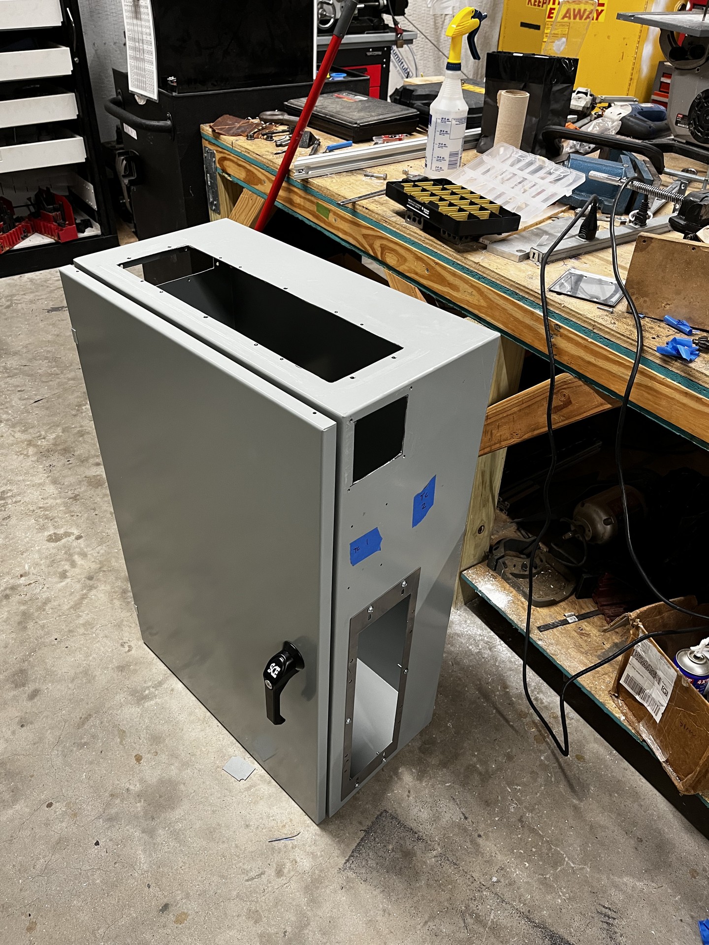
1. Cutting the Box
A jigsaw and angle grinder did most of the work here. Finished all edges with a file and a deburring tool for the smaller cuts.
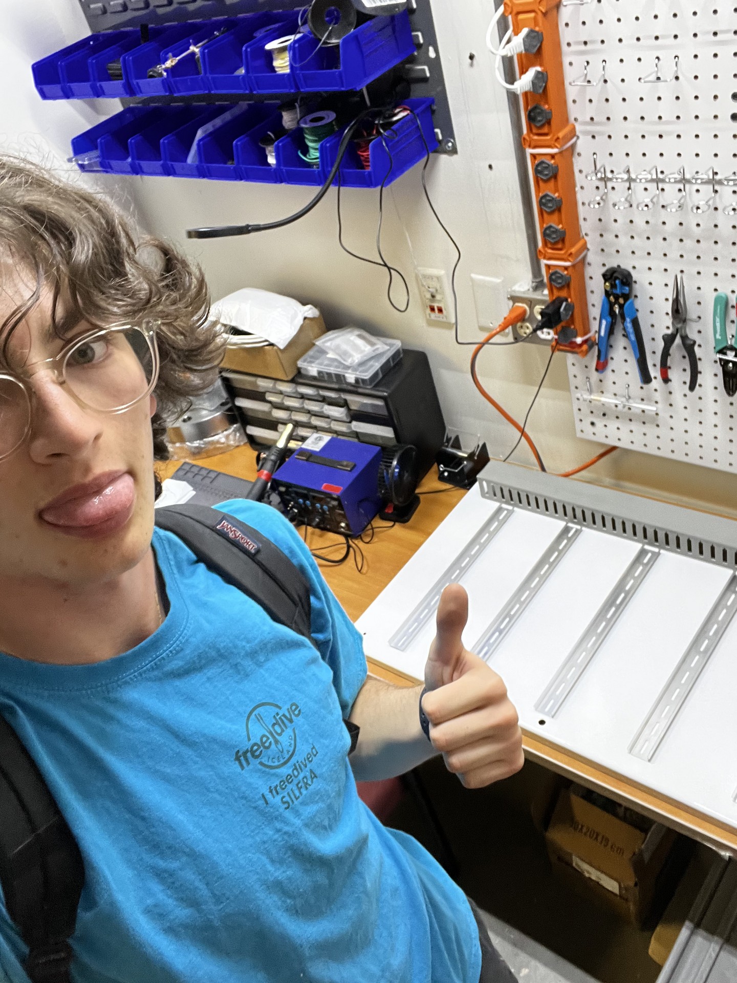
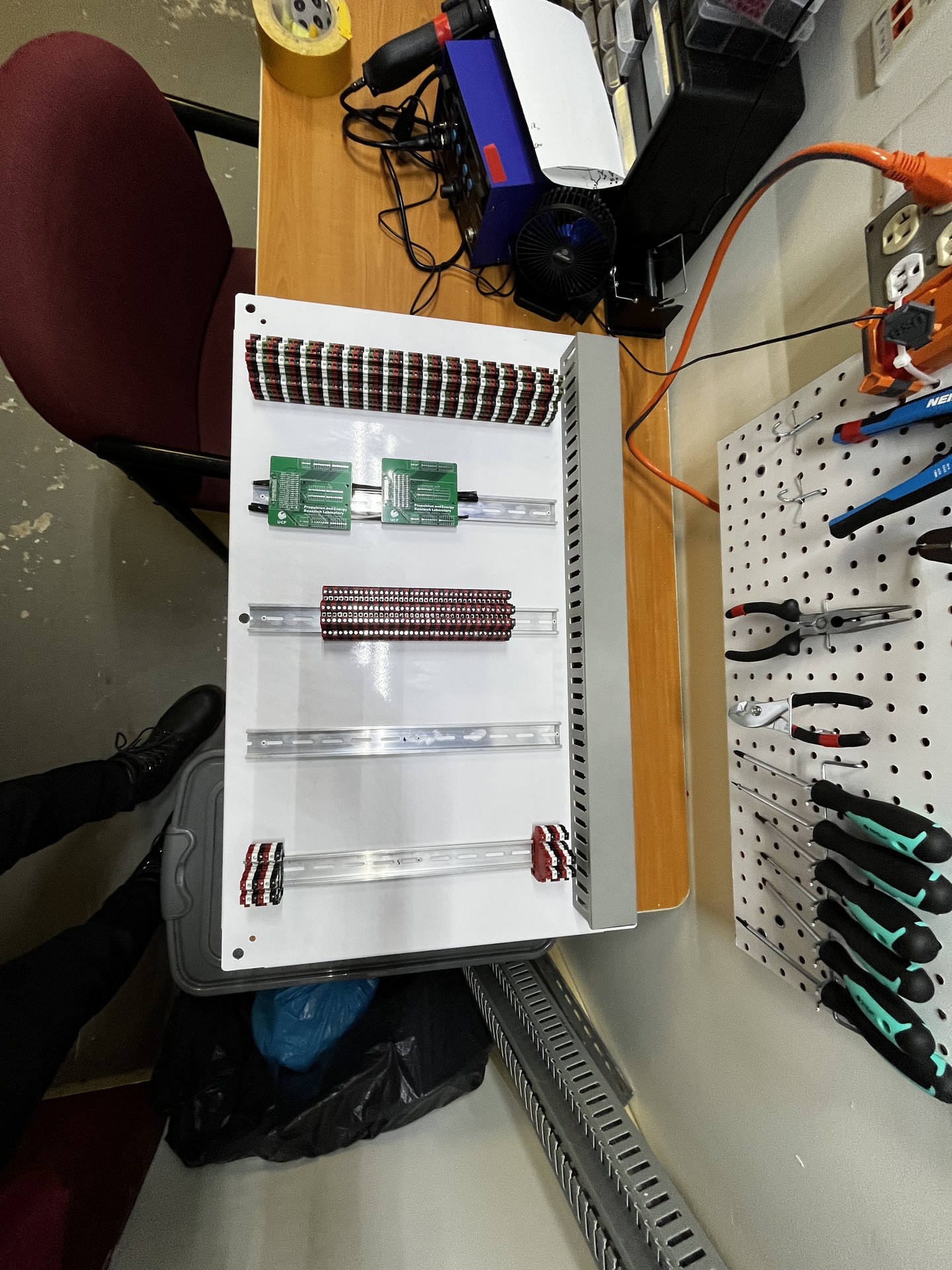
2. Panel Layout
Rivet DIN Rail + cable tray onto the steel back panel of the waterproof enclosure. Began mounting components to the DIN rail.
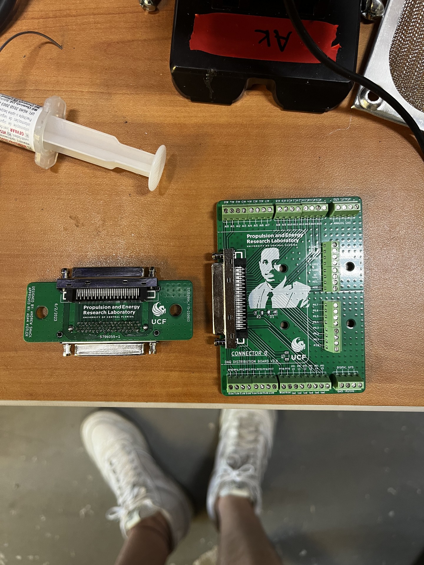
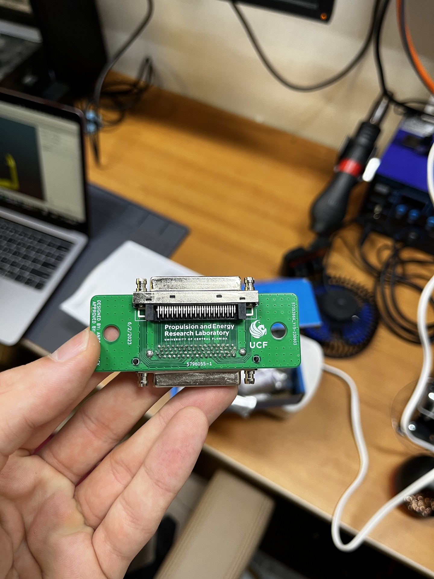
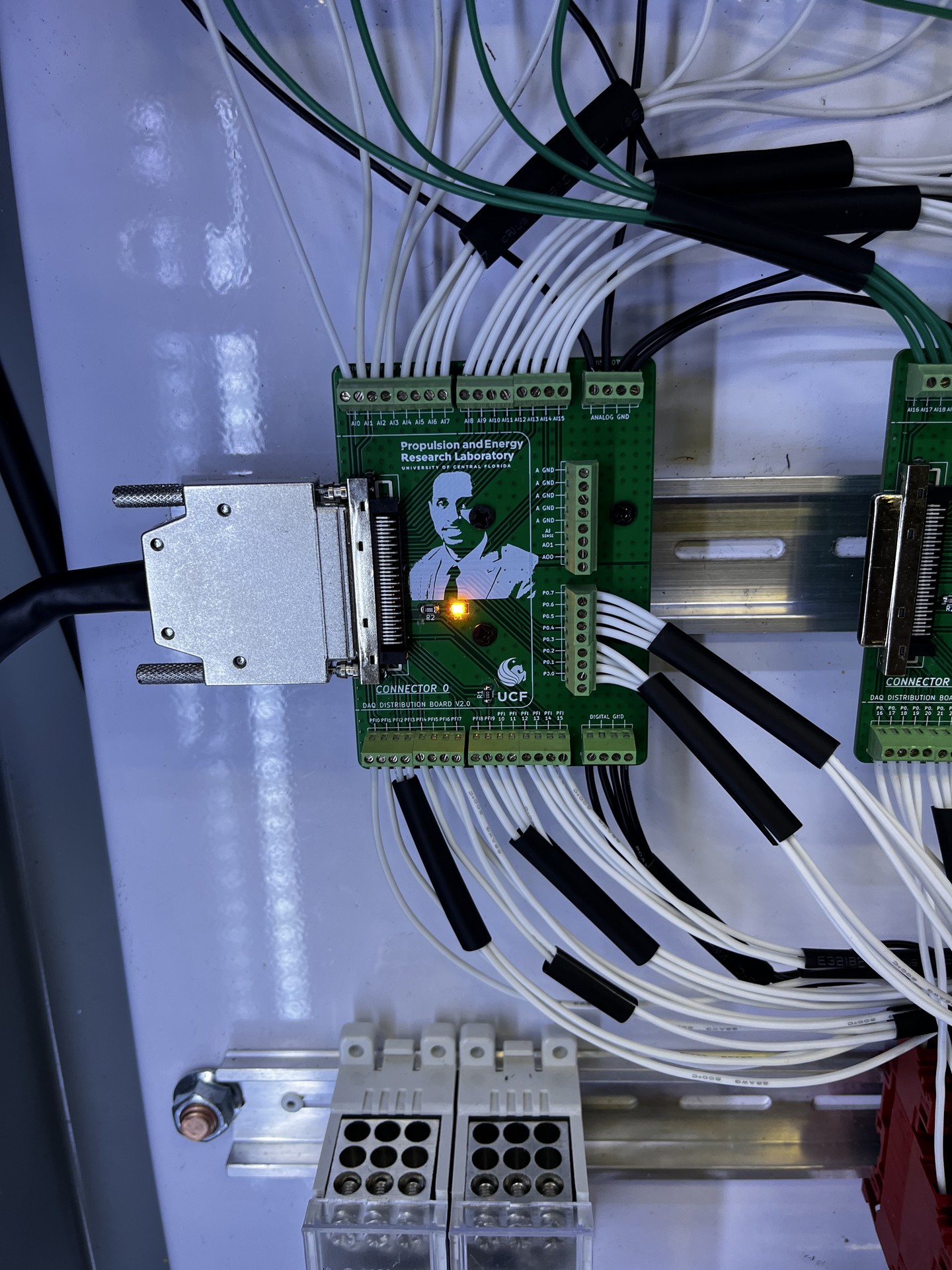
3. Custom PCB
To ease cable management within the box, I designed a custom PCB to break out the DAQ's D-SUB connector to terminal blocks in an orientation conducive to wire management. The first photo shows version one on the left, and version 2 on the right.
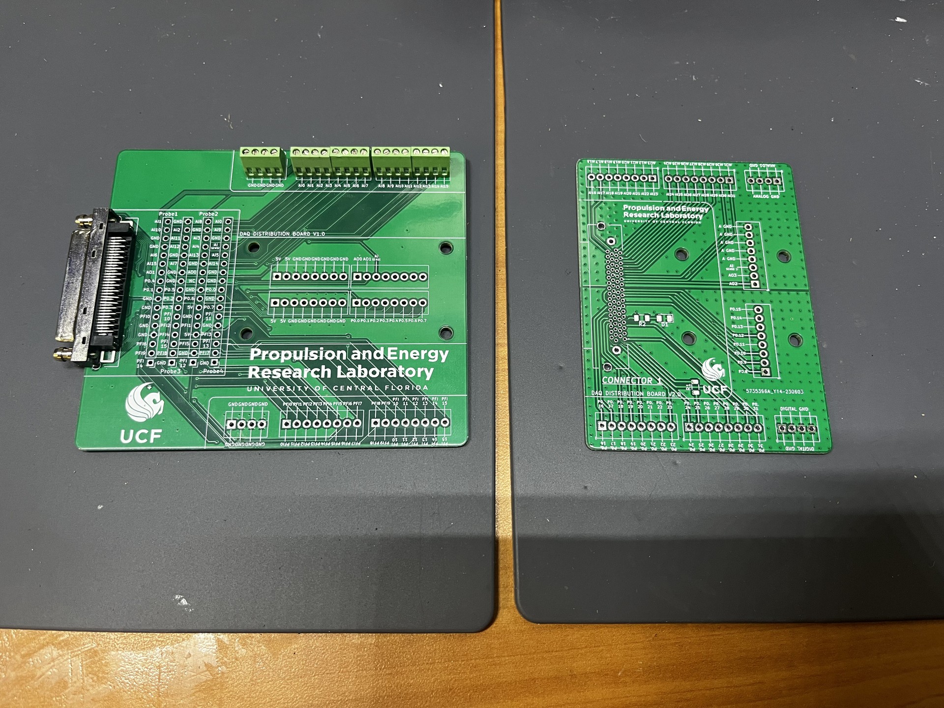
The version 1 PCB had grounding issues, which manifested during the first test with an analog pressure sensor. Major noise was observed when sampling data. I met with a friend who was an Electrical Engineering major, who gave me design feedback. V2 got proper ground planes with an array of vias between. V2 is shown below, smaller PCB is the equivalent to a bulkhead interface, to keep the box waterproof.
The bust on the PCB is Dr. Kareem Ahmed, the PI at PERL. This makes sure all of the data goes through him.
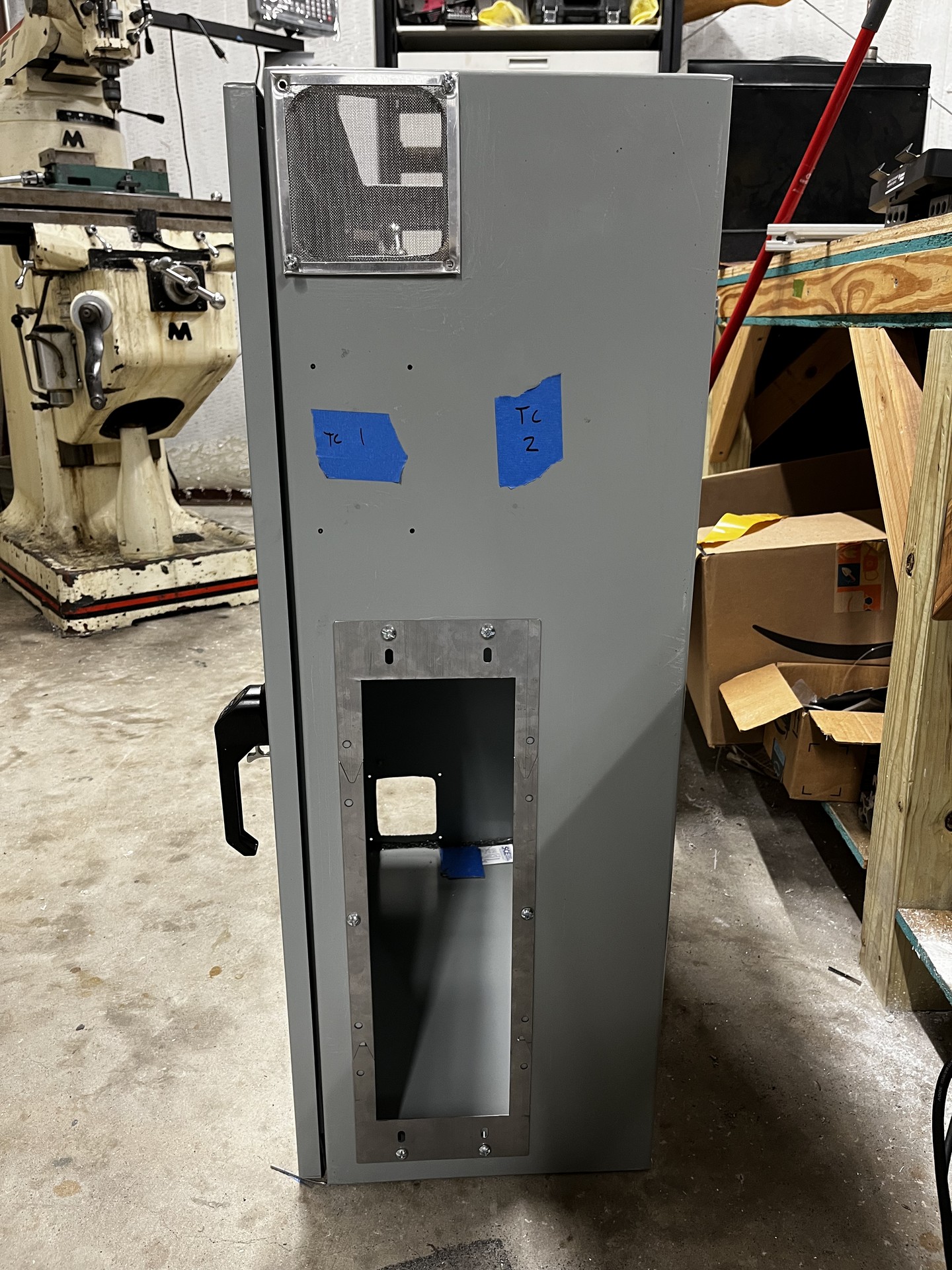
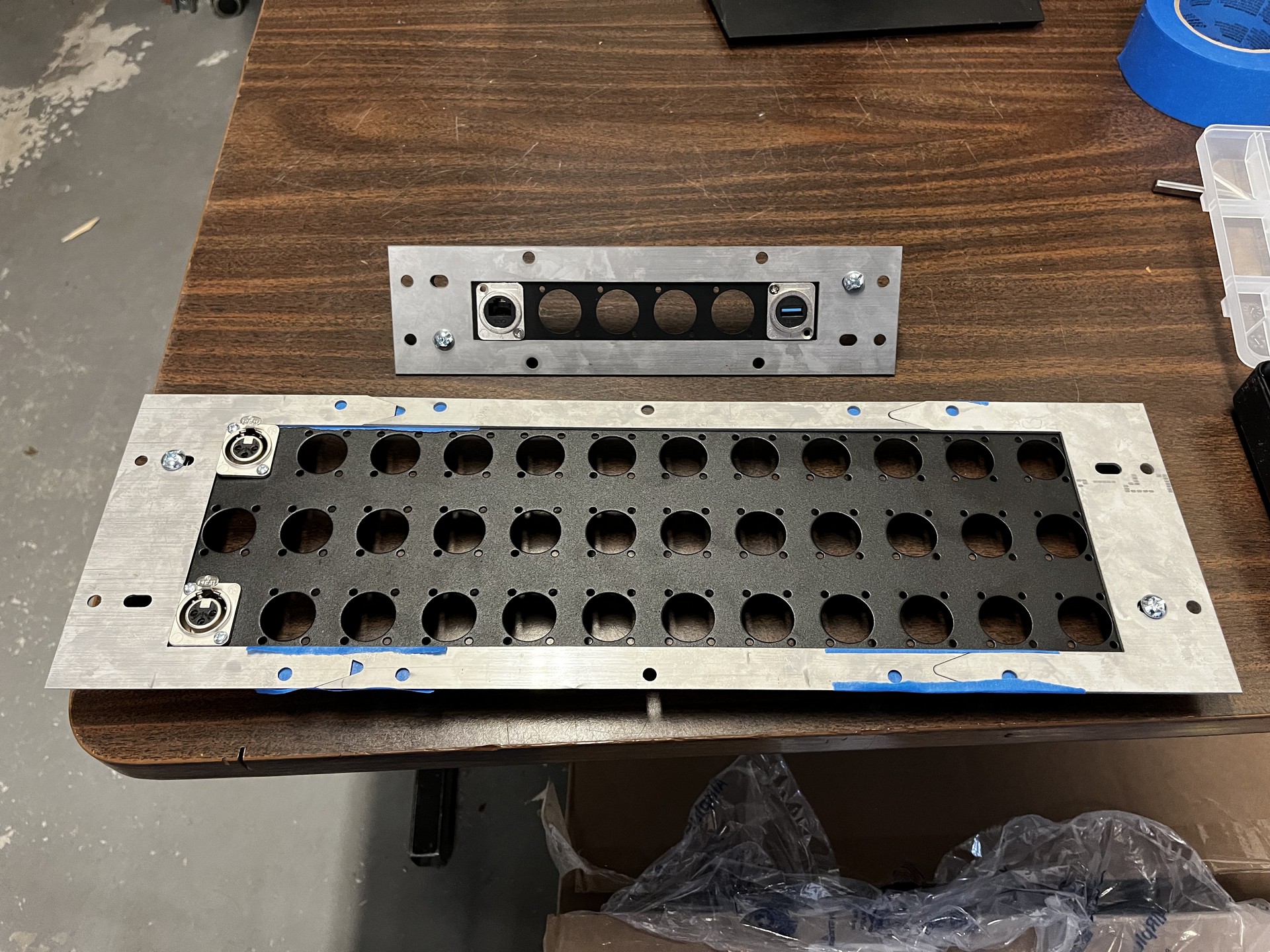
4. Water Jet Cut Interface Panels
I got trained on a water jet I had access to at the time, and utilized this to cut the waterproof steel panels shown below. These mount the XLR mounting panel to the box.
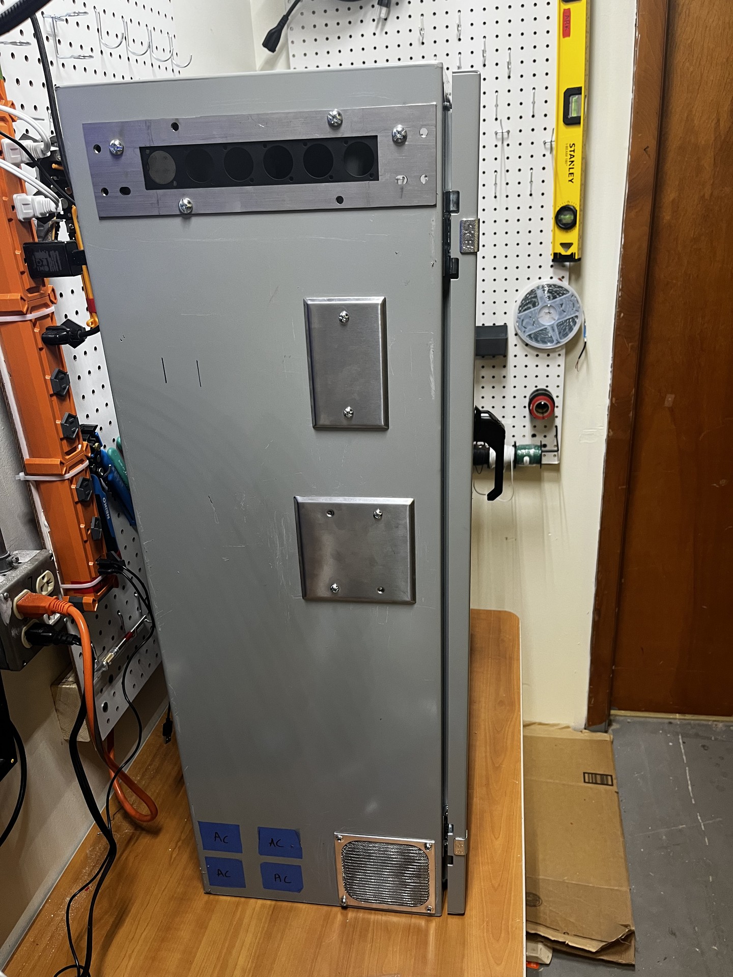
5. Assembling the Box
Mounting all the interface panels, for buttons, plugs, etc. Put the back panel in, and begin wiring.
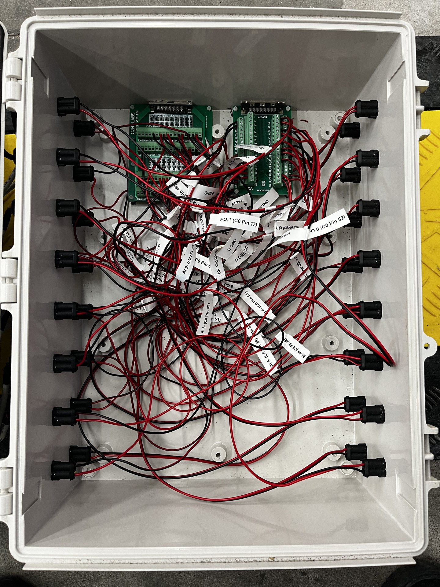
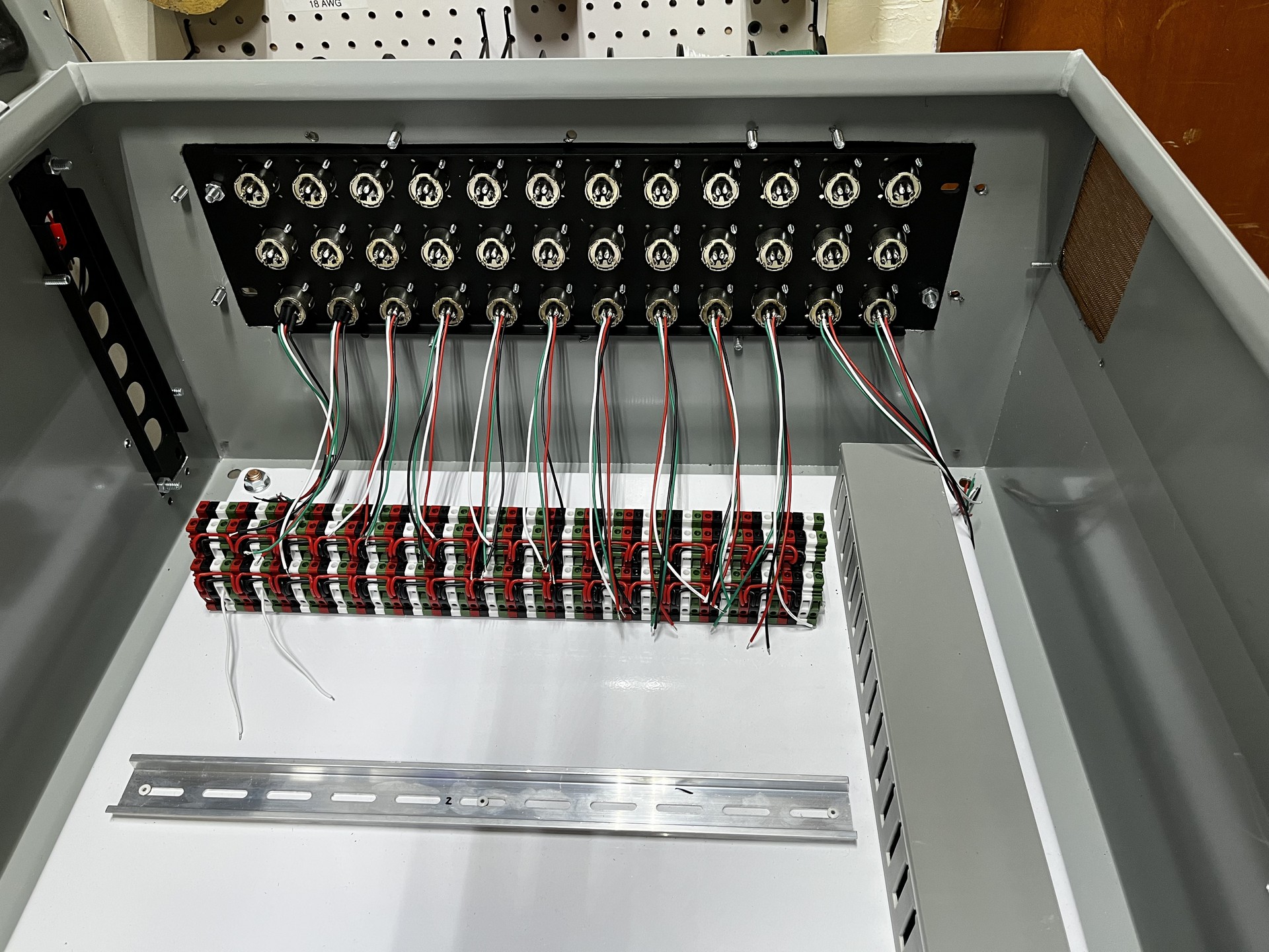
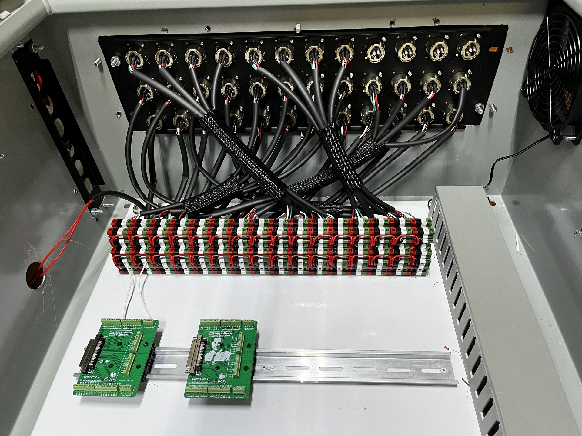
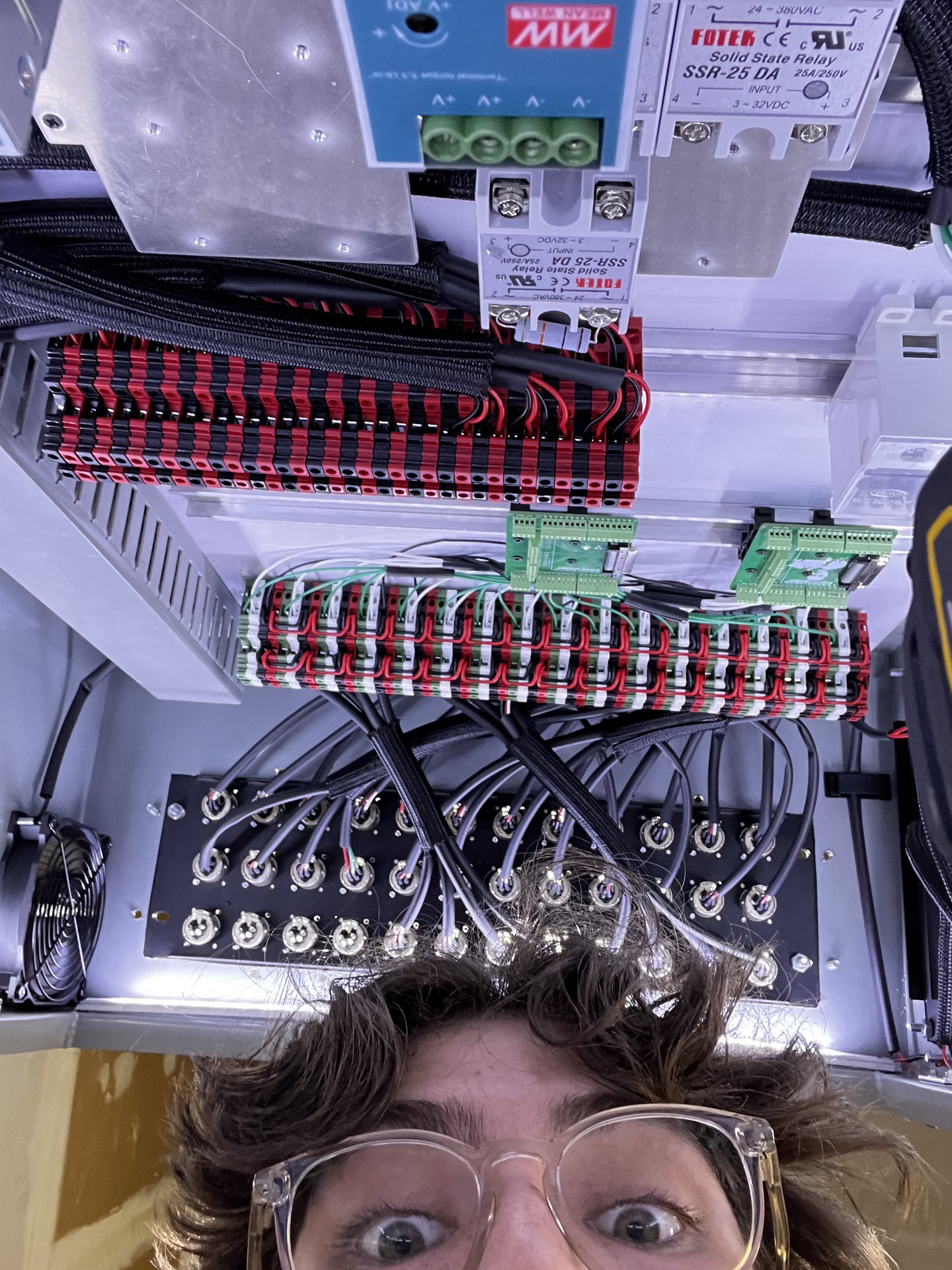
6. A lot of Wiring
Hours of soldering, heat shrinking, and cable management to keep organized.
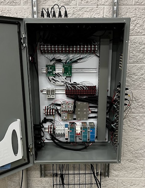
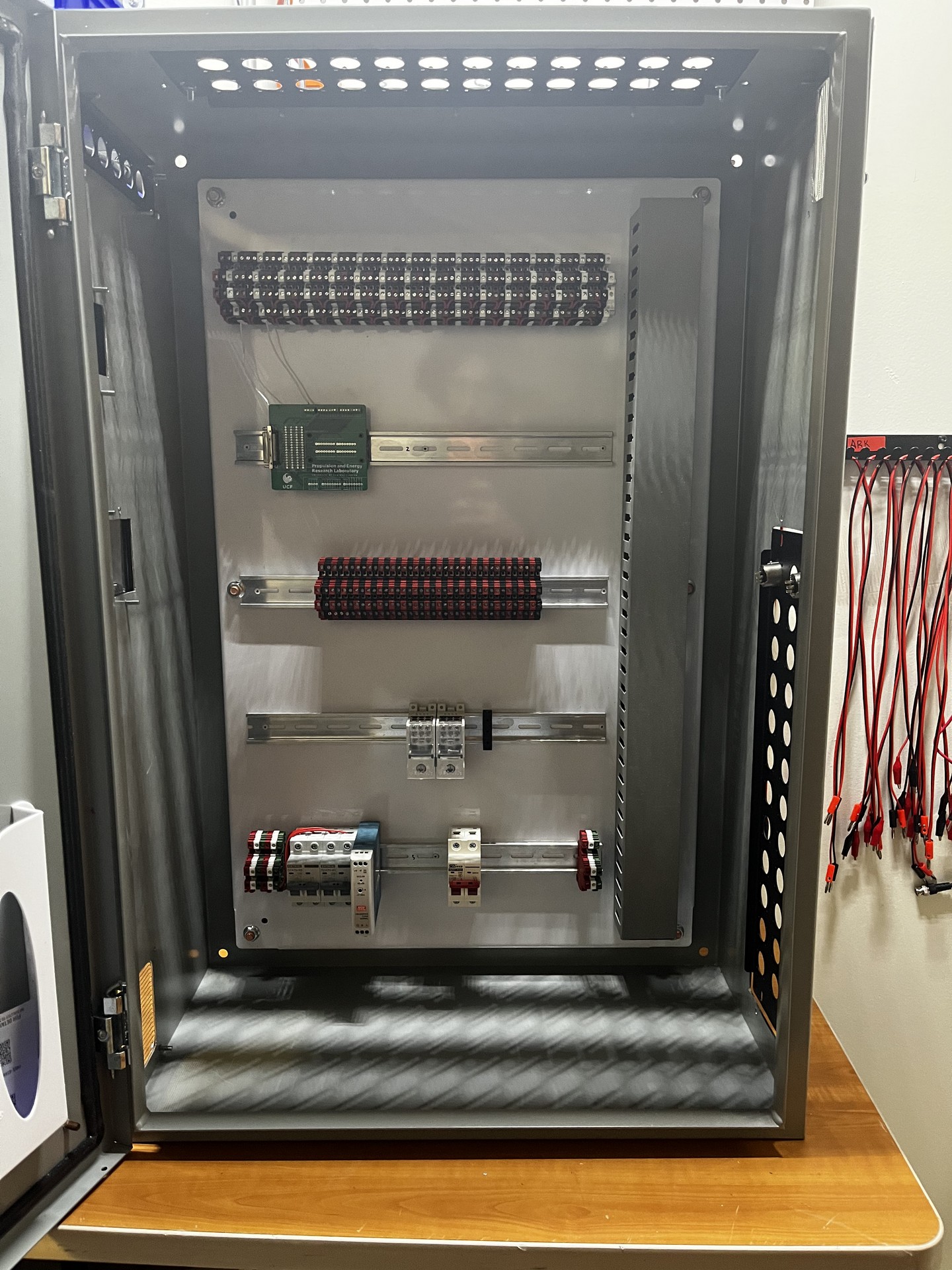
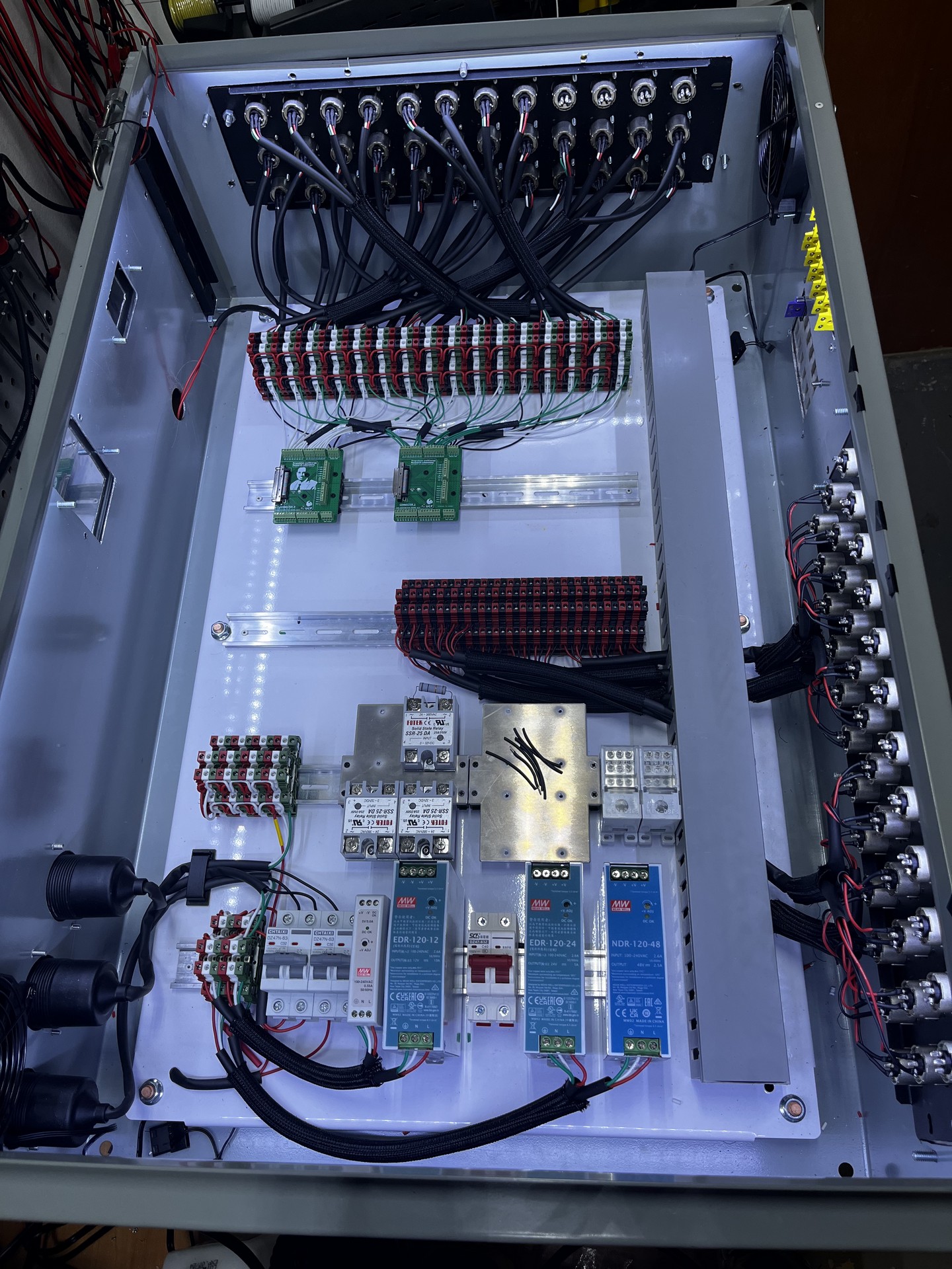
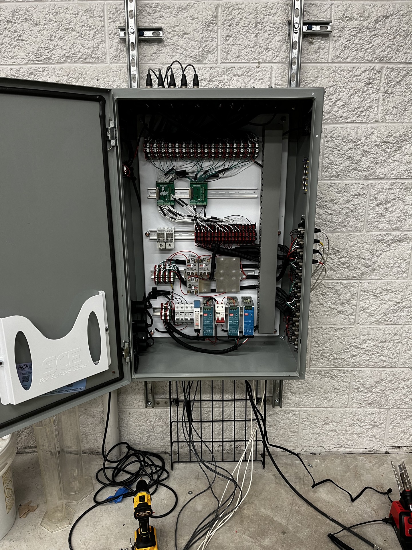
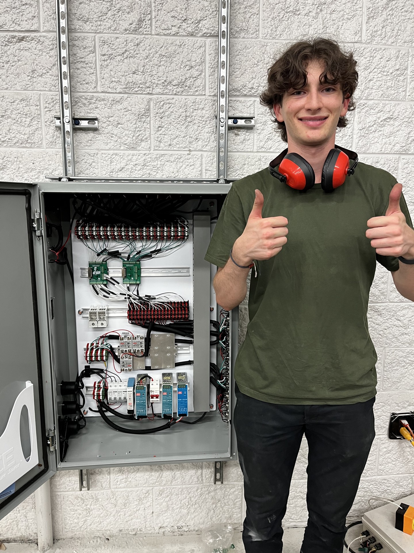
7. First Power On!
Got all of the power supplies in (5, 12, 24, 48 VDC for future capabilities), wired to independent breakers for safety cutoffs. Independent XLR panels for digital and analog signals, plus dedicated thermocouple ports (Type K & E). Got the first power on, no issues. LEDs provide nice, bright lighting to ease troubleshooting.
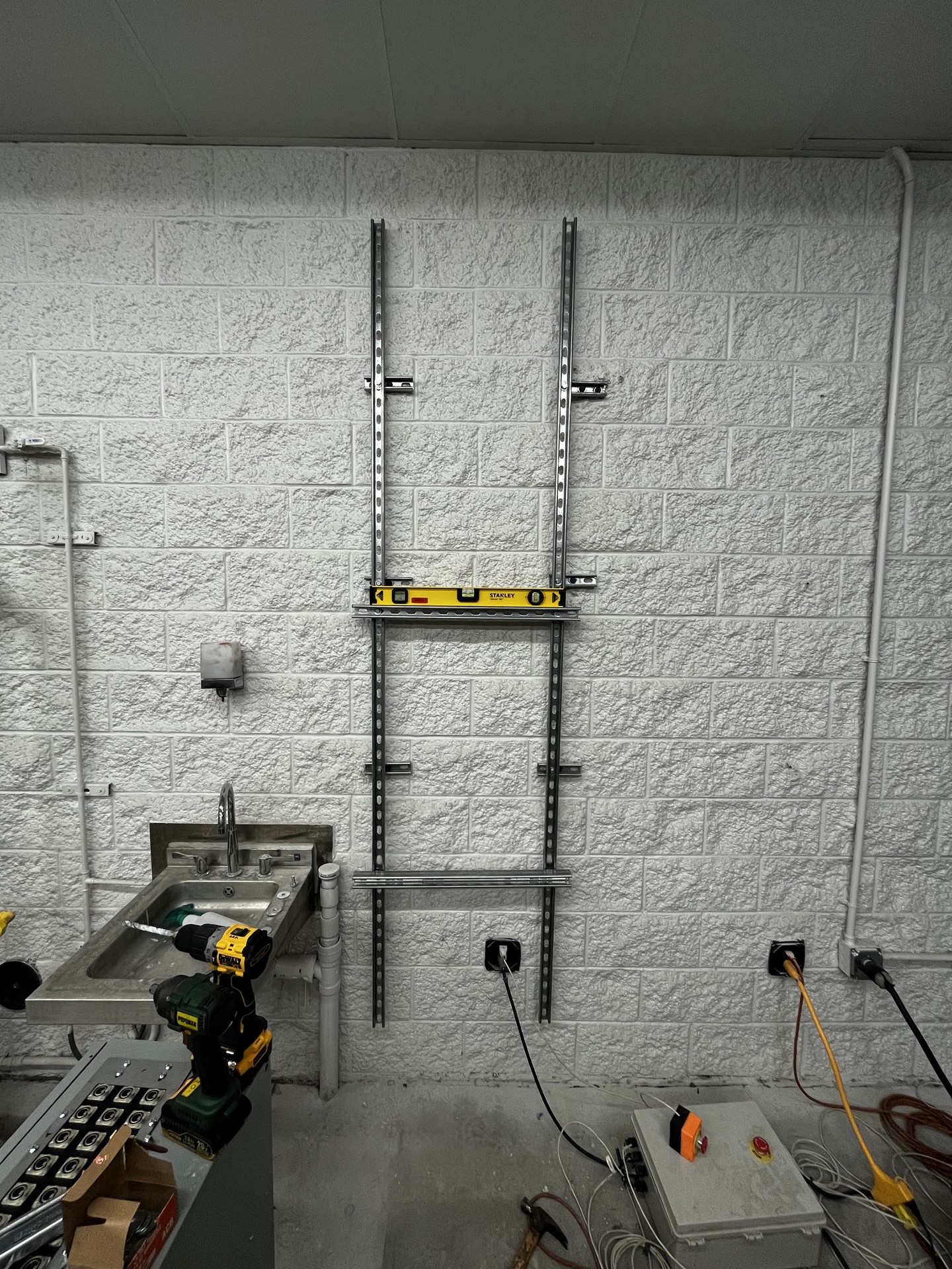
8. Mounting
Mounted a Unistrut frame on the concrete wall. The DAQ-BOX, along with the cable tray, got put up shortly after.
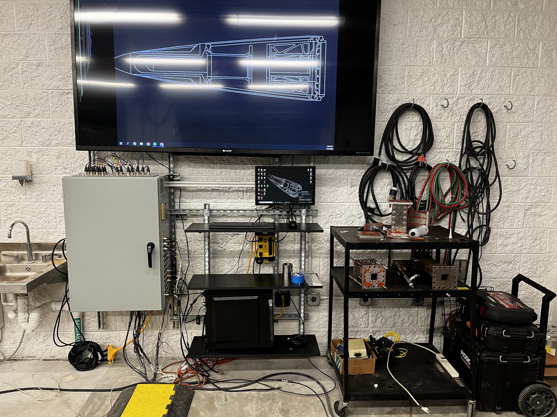
9. Final Configuration
Final test setup, 90" TV for a clear view of the high-speed cameras when setting up at the test stand, ~10' away.
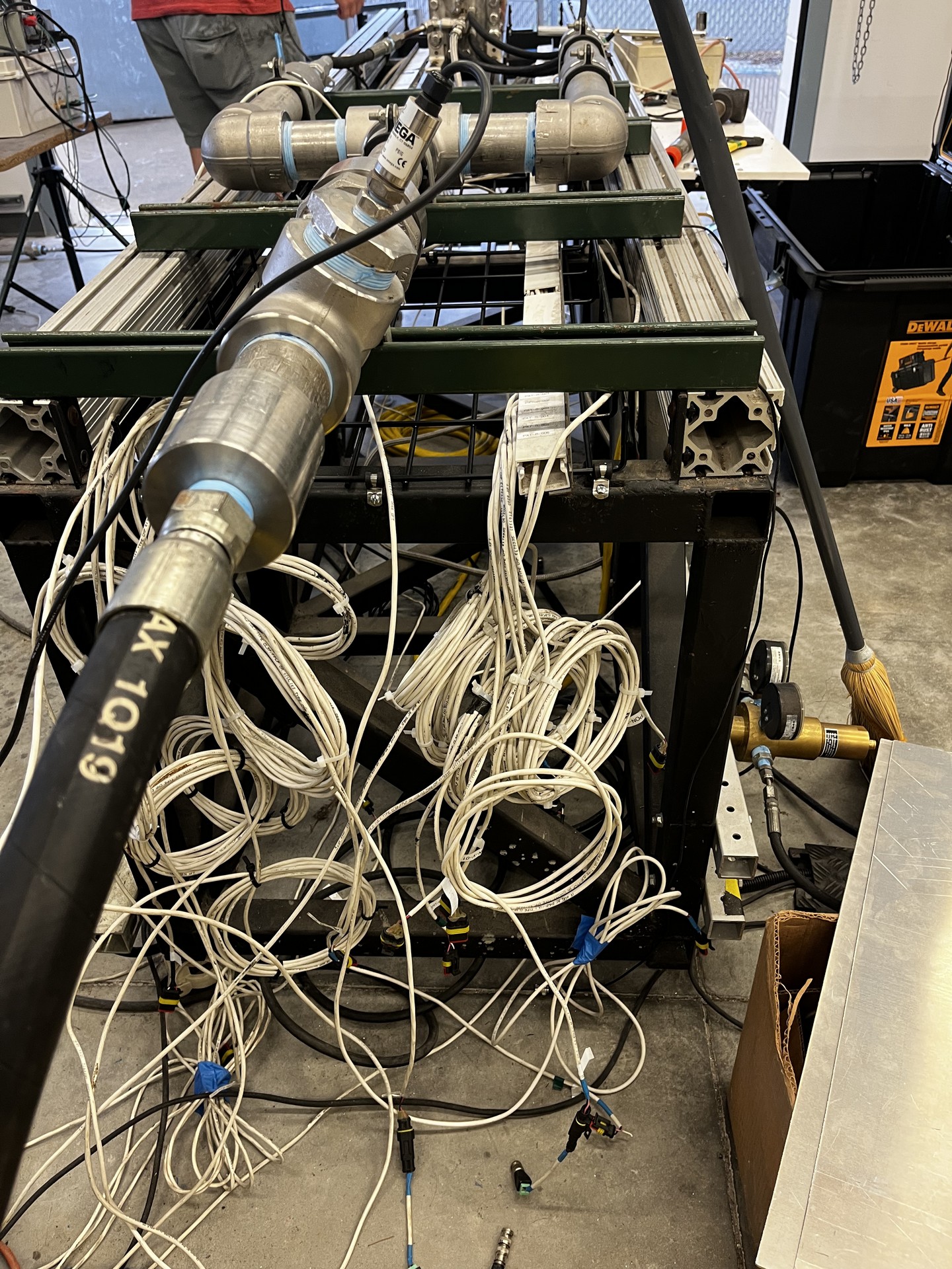
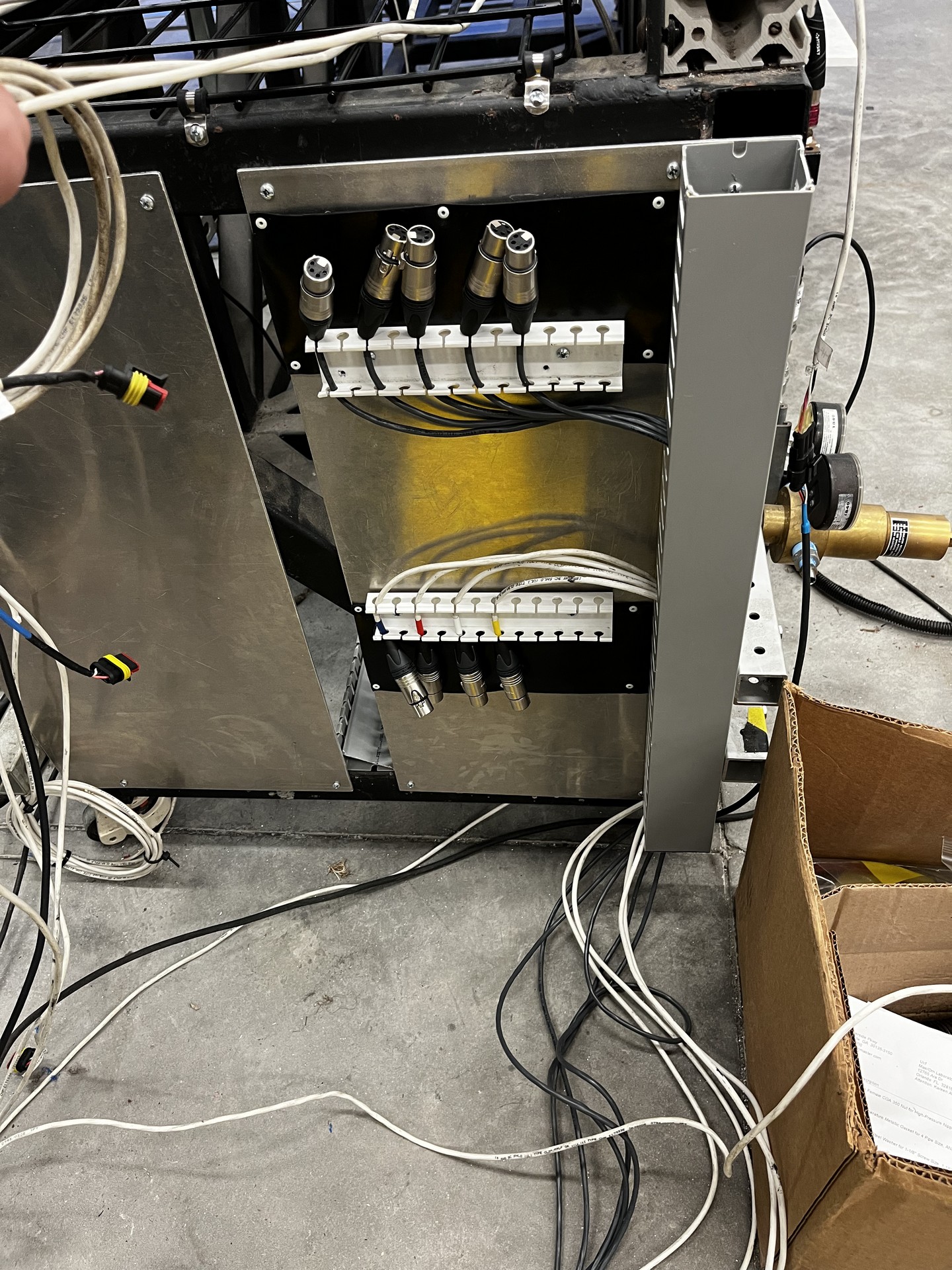
10. Test Stand Patch Panel
The first image is the old wiring configuration, connecting the last DAQ to the test stand. The right photo is the updated "patch panel", enabling a clean and modular interface between the two.
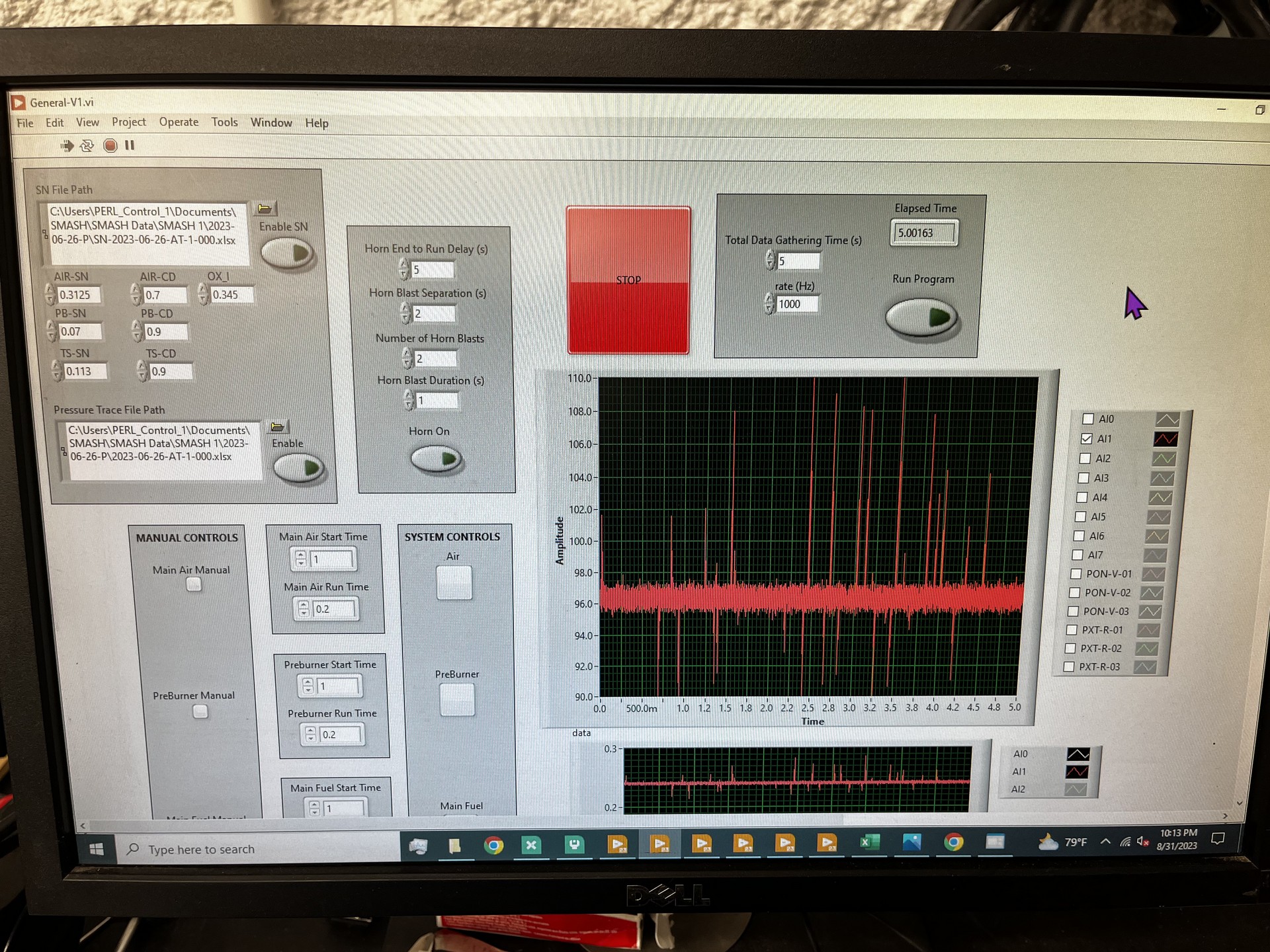
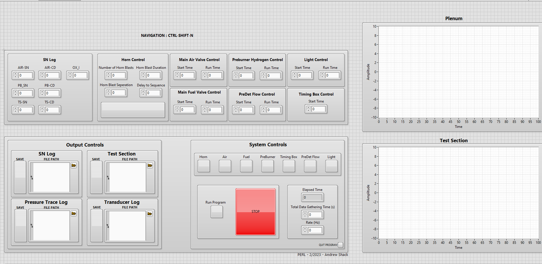
11. Custom LabVIEW VI
I developed a new LabVIEW program that interfaces with the DAQ-BOX to control the facility and acquire data during tests. Both photos show VI's I developed; the left photo is the V1 with the updated back end. The right photo shows the updated front end to increase efficiency and usability.
12. A look into the past
This is the old DAQ setup that was being utilized. It does not look the best, but it did function. I think we made a bit of an improvement.